MC/MICHAEL OS 89 C:\RECYCLED\MAGNETIC_ROTORS\ ← Desktop
EXPERIMENT_02.EXE / THE MAGNETIC ROTOR LAB

PERSONAL R&D / DIGITAL PROTOTYPE

Can magnets keep a rotor turning?

I designed two printable rigs to test that question. One stacks three magnet discs; the other places four movable magnetic gates around a single rotor. Both are meant to be measured, not believed on sight.

Result so far: CAD, manifold meshes and provisional slicer checks. No physical build or measured continuous run. Neither design is a demonstrated self-running motor.

CAD render of a single gold rotor between four colored adjustable gates on a square base
FIG. 02 / RADIAL TEST BEDCAD RENDER · NOT A PHOTOGRAPH

Where does the push go?

A nearby magnet can speed a rotor through one part of its turn and resist it elsewhere. A short burst of acceleration is easy to see; the useful test is the whole revolution, at the same rotor angle on successive laps. Moving a gate by hand changes the magnetic field, but that movement also exchanges energy with the system.

These designs make the gate position visible and adjustable so the behavior can be compared. The goal is a repeatable experiment in magnetic force, torque and losses—not a claim of energy created by permanent magnets.

Two layouts. One honest test.

DESIGN 02 / CURRENTDIGITAL ONLY
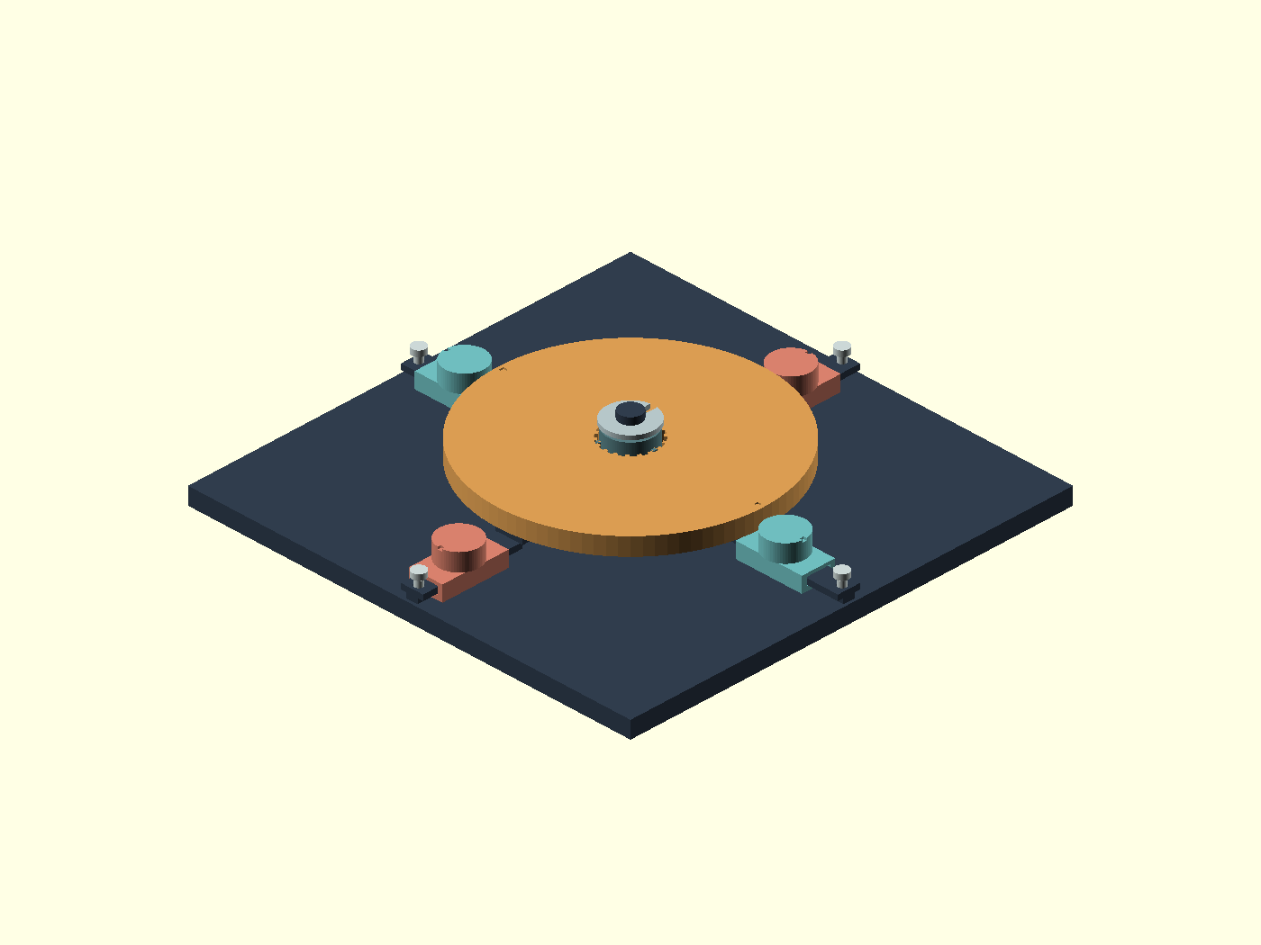
Radial design CAD assembly with four independently movable magnetic gates

Radial magnetic gate test bed

A Ø96 mm rotor carries twelve sealed Ø8 × 3 mm magnets. Four separate carriages each hold one more magnet and slide by hand on printed tracks. A printed post, sleeve, washer, clip and stop pins keep the thirteen assembly pieces together—no screws, glue, coils or external bearings.

  • Rotor12 alternating poles
  • Gates4 manually positioned
  • Magnets16 × Ø8 × 3 mm
  • Footprint160 × 160 mm nominal
Download design 02
DESIGN 01 / REFERENCEDIGITAL ONLY
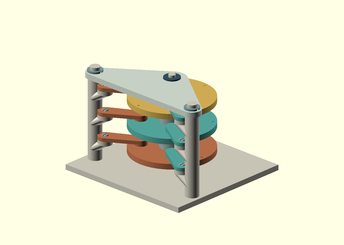
CAD render of three magnetized discs stacked between printed posts and manual gate arms

Three-tier stacked rotor

Three discs and pivoting gate arms explore whether staggered geometry changes the feel of a hand spin. The discs carry eighteen sealed magnets; six gate arms carry six more. The model uses manually positioned gates—not an automatic timing or energy-input mechanism.

  • Discs3 magnetized tiers
  • Gates6 arms, positioned by hand
  • Magnets24 × Ø8 × 3 mm
  • Assembly24 printed pieces
Download design 01

Attraction here. Barrier there.

The radial rotor alternates N-up and S-up poles every 30°. Four gate magnets sit at the compass points with N/S/N/S-up orientation, viewed from the printed top. Colored circles in this diagram expose hidden cavities for illustration only; finished parts have uninterrupted printed roofs.

A point-dipole approximation predicts positions that attract, repel and settle. Across an ideal complete turn at a fixed gate setting, the modeled magnetic work returns to approximately zero. Friction turns useful motion into heat. Moving gates can supply or absorb work; it is not a free extra push.

Model uses assumed magnet properties, not measured magnets or finite-element validation. Tesla-era “aether” language is historical context, not an additional force law demonstrated by these files.

Digital cutaway showing twelve alternating rotor poles and four outside gate poles; the colors are illustrations of sealed magnets
● N-up   ● S-up · digital cutaway

The next proof is physical.

01 / Fit first

Print and measure a pocket coupon with a real magnet, then test one track, carriage, sleeve and clip. Nominal CAD clearances do not establish reliable retention or fit.

02 / Pause before roof

The provisional Bambu Studio 3MF projects carry insertion pauses. Re-slice for the actual printer, nozzle, filament and plate; inspect the pause immediately before each cavity roof. STL meshes alone do not carry pauses.

03 / Mark poles before sealing

Check every magnet with a known reference pole. Radial rotor: N/S alternating from the CAD +X pocket; the +X and −X pockets are both N-up. Gates at right/top/left/bottom: N/S/N/S-up. The physical fiducial marks form after the insertion pause; use a verified slicer orientation, not a mark that is not yet printed.

04 / Measure full laps

Hand-start under comparable conditions. Record passage of one mark at the same angle on successive revolutions; compare gate settings and account for every manual adjustment.

Inventory note: design 01 takes 24 magnets and design 02 takes 16. Both together use all 40 nominal Ø8 × 3 mm magnets in the available inventory, leaving none for a permanently sealed coupon.

Files for inspection and iteration.

Each ZIP contains the exported STL parts, editable OpenSCAD source, provisional 3MF projects and a print-status README. Multiply repeated parts per README. These are research prototypes, not prequalified print jobs.

Radial magnetic gate test bed9 mesh kinds · 13 assembly pieces · 16 magnets
Download ZIP
Three-tier stacked rotor14 mesh kinds · 24 assembly pieces · 24 magnets
Download ZIP

No physical print, fit, roof-bridge, torque or spin-time result yet. Real printer settings and actual magnet dimensions must be checked before printing. A Recycle Bin shortcut keeps this page off the main desktop; the page and files are public to anyone with the URL.